|
LOADING DIAGRAMS
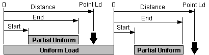
A load diagram is a working sketch of the loads present on a structural member and is recommended before tackling a complex loading problem. The diagramming convention is to select one end of the member as the left end and locate the loads and their distances toward the right. Beams that overhang a support at one end are shown at the right. The reactions at the supports may be of different magnitudes and you'll need to keep them organized as they may be used or accumulated for a beam or post load later in your design analysis. The left reaction is called R1, the right reaction is R2. The reactions are the locations of the supports such as a wall or post under the member. By identifying the distance, or start and end locations, in relationship to the reactions the loads can be accurately placed on the structural member.
Note: Overhangs are often referred to as cantilevers by the building trade. In structural design, a cantilever is a whole different animal and should not be confused with overhanging structural members.
|
|